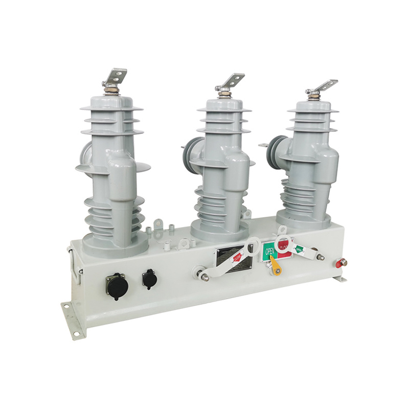
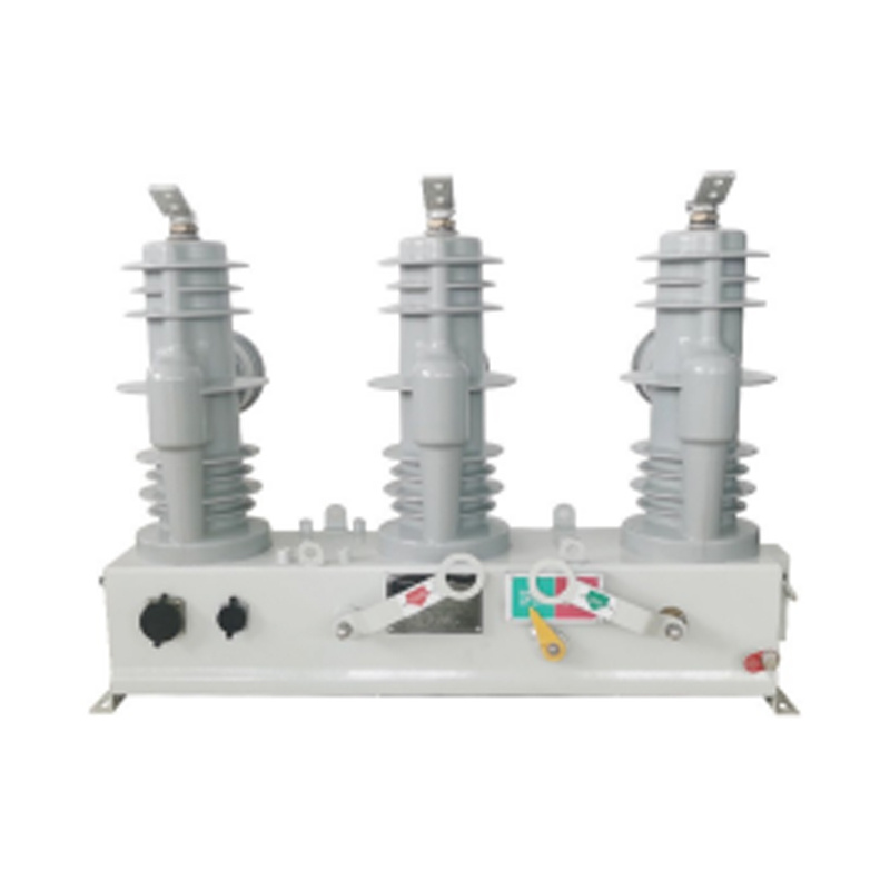
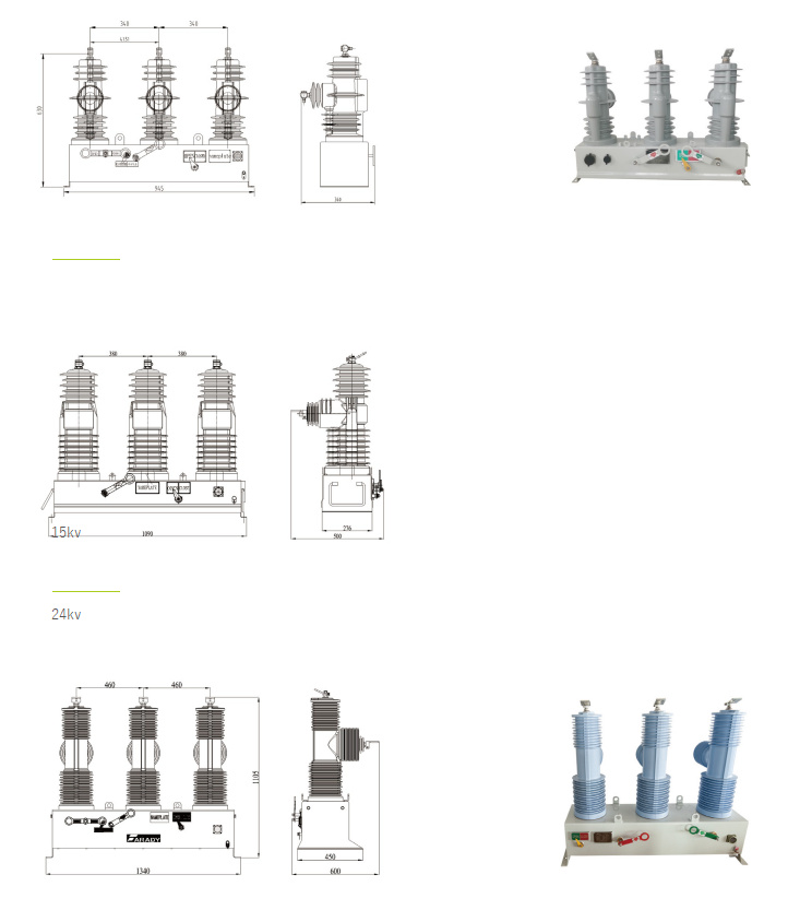
FAR series 15KV/27KV/38KV AUTO Circuit Recloser
Model Series
ACR
Rated Voltage
2.5~34.5kV
Standard
IEC 62271-1
Warranty
Two years
Application
Outdoor/Indoor
The FAR series Auto circuit recloser integrates the functions of control, protection, measurement,communication,fault detection,on-line monitoring of closing or opening.comply to IEC62271 and ANSI/IEEE C37.60 standard.
 General
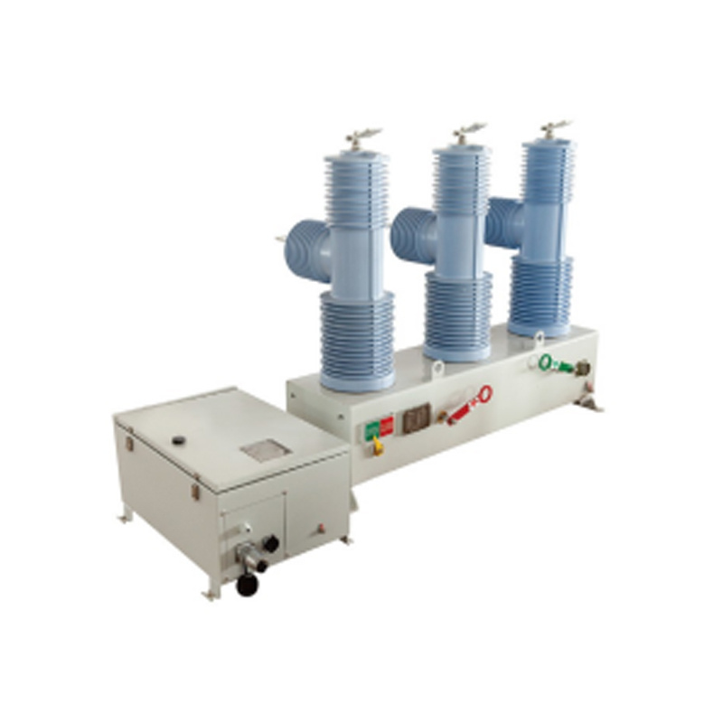
Farady Electric strives to bring our customers the latest technology and competitive pricing and best service for pole mounted Auto circuit recloser.
The FAR series Auto circuit recloser can use on overhead distribution lines as well as distribution substation applications for all voltage classes 11kV up to 38kV at 50/60HZ power system. And its rated current can reach 1600A.
Service Condition
- Air temperature: Maximum temperature: +85℃; Minimum temperature:-45℃.
- Humidity: Monthly average humidity 95%; Daily average humidity 90% .
- Altitude above sea level: Maximum installation altitude: 2500m or more higher.
- Ambient air not apparently polluted by corrosive and flammable gas, vapor etc.
- No frequent violent shake.
Product Structure
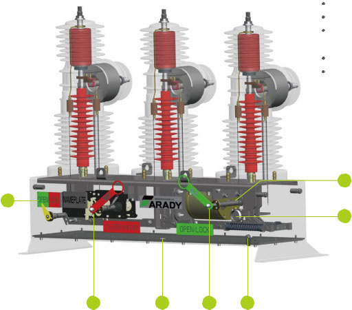
| 1 | ON/OFF Indicator | 2 | Emergency Close | 3 | Counter |
| 4 | Manual OFF | 5 | Earthing | 6 | Secondary Socket |
| 7 | Magnet Mechanism |
Production's Characters Description
- High quality Solid Epoxy resin material
- Fully comply with ANSI std
- Guarantee 30,000 times operation Environment friendly , Oil / SF6 Gas free
- Suitable for both Pole mounted or Substation available
- Reliable and Enhanced Life Expectancy
- Ambient temp: -40℃~80℃
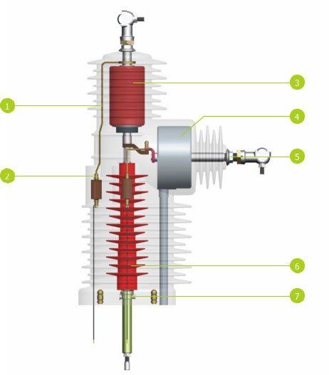
| 1 | Rogowski coil | 2 | Voltage Sensor | 3 | Vacuum Interrupter |
| 4 | CT | 5 | Conductor | 6 | Push Rod |
| 7 | Push Reed |
Production's Characters Description
- High quality Vacuum Interrupter
- Voltage sensor Integrated
- CT Integrated
- Reliable Push rod
- Minimized moving components
- Maintenance free design
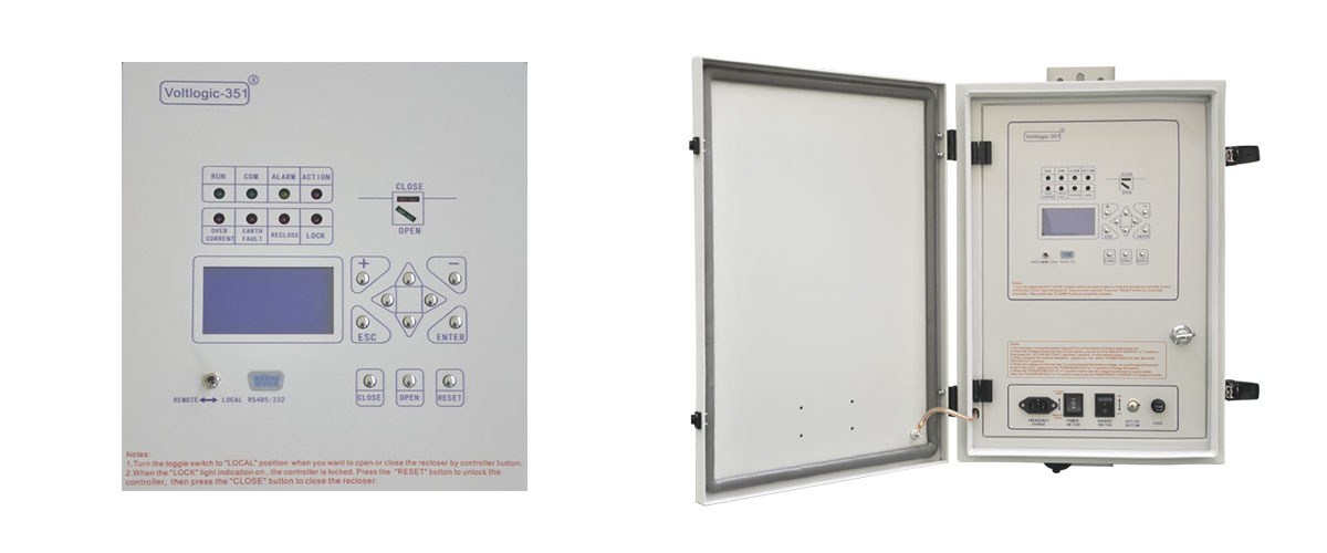
Controller
1.1 Description
1.Voltlogic-351 series recloser controller is medium voltage overhead line grid monitoring unit, It can combined with vacuum circuit breaker for achieve of automatic reclose, measure monitoring, fault analysis and event records. It gives us a safety power grid for cutting line fault and automatic recovery operation and power automation.
2.The controller is suitable for up to 38kV outdoor switchgear using, include: vacuum circuit breakers, oil circuit breakers and gas circuit breakers.
3.The controller is gathering with line protection, control, measurement and monitoring of voltage and current signals integrated automation and control devices outdoors.
4.The controller is a automatic management unit for single way/multi ways/ring network/two power sourcing, provided with all voltage and current signals and all functions.
5.The controller column switch intelligent controller supports:
Wireless (GSM/GPRS/CDMA), Ethernet mode, WIFI, optical fiber, power line carrier, RS232/485, RJ45 and other forms of communication, and can access other station premises equipment (such as TTU, FTU, DTU, etc.).
1.2 Protection functions
| Protection functions | ANSI code | Name in Device |
| Phase overcurrent | 50P | P.OC |
| Overload | 49 | Overload |
| Phase Time-Overcurrent | 51P | P.Curve |
| Ground Overcurrent | 50G/N | E.F |
| Recloser | 79 | Reclose |
| Phase overcurrent cold load pick-up | CLPU 50 | Cold Load |
| Switch-Onto-Fault | SOTF | |
| Undervoltage | 27 | Under volt |
| Overvoltage | 50P | P.OC |
1.3 Metering
1.Phase current IA, IB, IC RMS, Zero Sequency
2.Voltage Uab,Ubc,Uca,U0
3.Active power, reactive power and power factor
4.Frequency
1.4 Control and monitoring
| Circuit breaker control | 94 |
| Latching /acknowledgement | 86 |
1.5 Features
A.Protection configuration is complete, and all protection functions can be switched on and off fiexibly.
B.6 channels signal input.
C.4 channels current measure.
D.4 channels voltage measure.
E.Large capacity flash memory can record at least 100 times of historical events, and no data will loss even the power is off.
F.Circuits operating loop can be used both the direct or alternating current, self-adaptation open/close brake function, which can co-work with various of breakers, and the operation is simple and reliable.
G.The device has complete self-inspection function to in-service monitor the working conditions of various parts of the device, ensuring the reliability of the device.
1.6 Records
A.Trip logs
B.SOE logs
C.Alarm Logs
1.7 Communication
1.RS485, RS232 port and Ethernet
2.Protocols -IEC60870-5-101, IEC60870-5-104 IEC61850 or Modbus RTU,DNP3.0
1.8 HMI Software
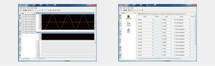
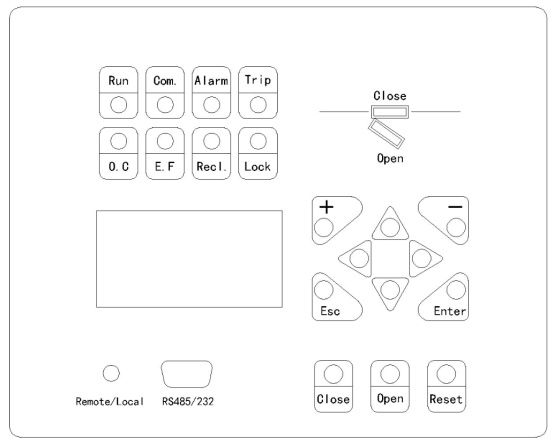
User Interface
The operator interface is designed to provide a r friendly method of controlling to user, viewing menus, entering settings and retrieving data from the relay. Four buttons are provided for navigation around the menu structure.
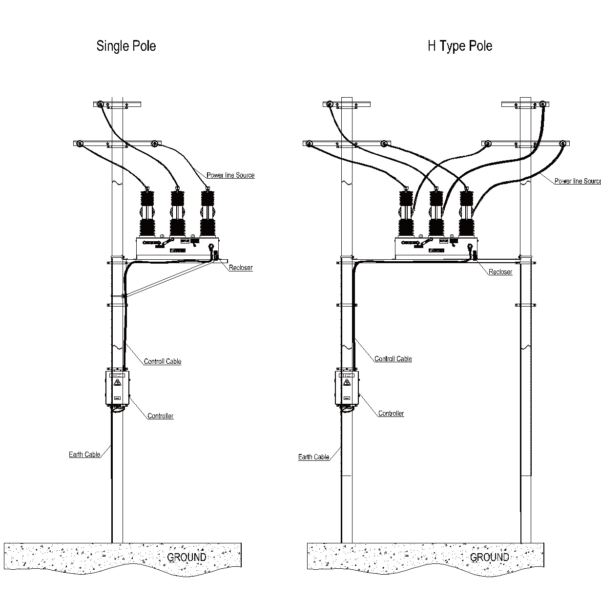
Projects
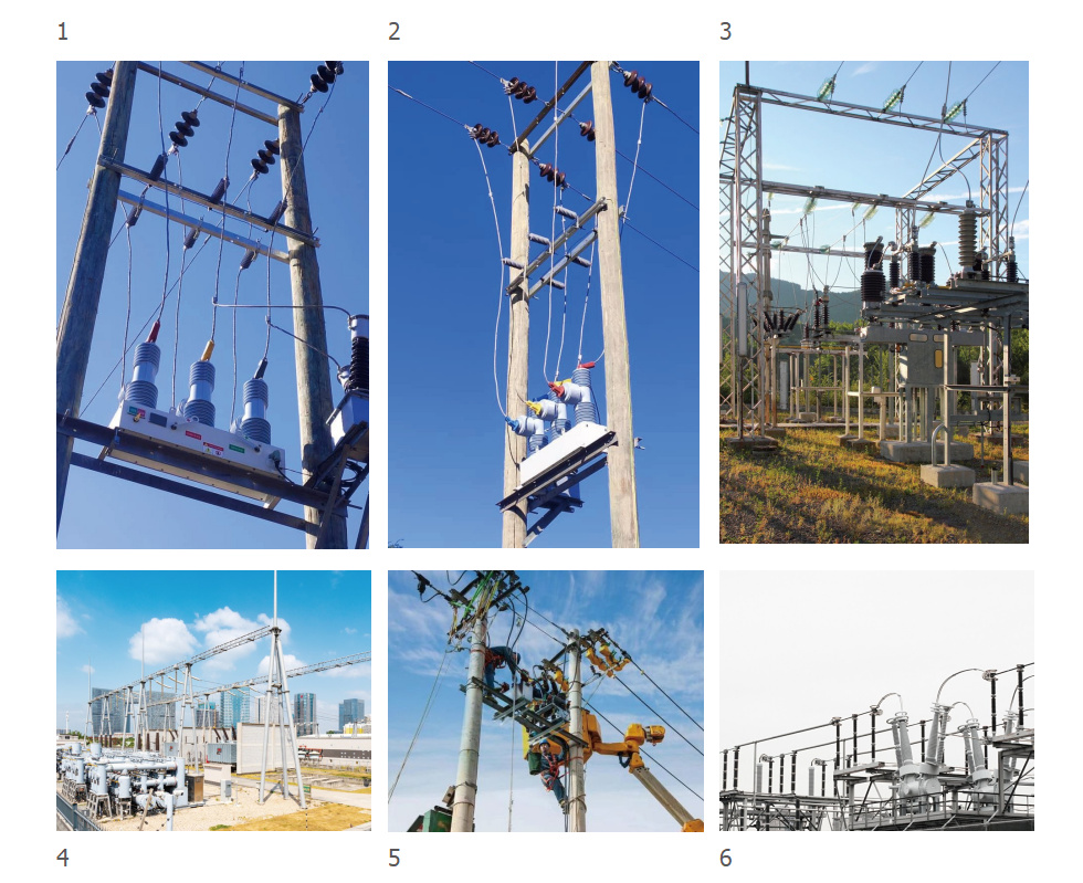
Installation
Technical Data
| No. | Item | Unit | Data | ||
| 1 | Rated voltage | kV | 15 | 27 | 38 |
| 2 | Rated current | A | 630 | 630 | 630 |
| 3 | Rated frequency | HZ | 50/60 | 50/60 | 50/60 |
| 4 | Power frequency 1min Dry | kV | 50 | 65 | 70 |
| 5 | Lightning impulse withstand voltage(peak value)alternate, | kV | 110 | 150 | 180 |
| 6 | Rated short circuit breaking current | kA | 16/25 | 16/25 | 16/25 |
| 7 | Rated short current switching current(peak value) | kA | 50 | 50 | 50 |
| 8 | Rated peak value withstand current | kA | 50 | 50 | 50 |
| 9 | 4S short time withstand current | kA | 20 | 20 | 20 |
| 10 | Rated operating circulate | kV | O-T1-CO-T2-CO-T3-CO-T4-CO Or Customize | ||
| 11 | Breaking current frequency under rated short circuit | times | 30 | ||
| 12 | Mechanism life | times | 30000 | ||
| 13 | Secondary loop 1 min power frequency withstand voltage | kV | 2 | ||
Technical Data
2.1Inputs and Outputs
Phase Current Inputs
| Parameter | Range |
| Quantity | 3 |
| Rated Current In | 5A |
| Measuring Range | 20×In |
| Instrumentation≥0.1×In | ±1%In |
| Frequency | 50/60Hz |
| Thermal Withstand: Continuous 10 Second 1 Second | 2×In 10×In 40×In |
| Burden @ In | ≤0.2VA (5A Phaseelement) |
Sensitive Earth Current Inputs
| Parameter | Range |
| Quantity | 1 |
| Rated Current In | 1A |
| Measuring Range | 2×In |
| Instrumentation≥0.1×In | ±1%In |
| Frequency | 50/60Hz |
| Thermal Withstand: Continuous 10 Second 1 Second | 2×In 10×In 40×In |
| Burden @ In | ≤0.02VA (1A Earthelement) |
Voltage Inputs
| Parameter | Range |
| Quantity | 3 |
| Nominal | 40�264Vrms |
| Operating Range | 0...264Vrms |
| Instrumentation≥0.8×Vn | ±1%Vn |
| Burden @ 110V | 0.06VA |
| Overvoltage Withstand | 280Vrms |
Auxiliary Supply
| Parameter | Range |
| DC Voltage | 220V Range 110 to 265V |
| AC Voltage | 220VAC50/60Hz Range 165 to 265Vrms AC 50/60Hz +5% |
| Power consumption | ≤100W/300W |
2.2 Unit Design
| Parameter | Range |
| Indication | 16 Character 8 line Display 10 LED s |
| User Interface | 11 Navigation Keys |
| Weight | 25kg |
2.3 COMMUNICATION
| Parameter | Range |
| Communication Port | RS485,RS232,Ethernet |
| Protocols | IEC60870-5-101 IEC60870-5-104 IEC61850 MODBUS RTU |
2.4 Data Storage
| Parameter | Range |
| Events | 1000 times |
| Storage time | 60days |
2.5 Climatic Tests
Temperature --- IEC 60068-2-1/2
| Parameter | Range |
| Display range | -25°Cto+60° |
| Storage range | -40°Cto+70° |